SEG-Y revision 2.0 Data Exchange Format, SEG Technical Standards Committee, January 2017
SEG-Y revision 1.0 Data Exchange Format, SEG Technical Standards Committee, May 2002
SEG-Y revision 0 (rev0), in the top row, starts with a 3200-byte textual (human-readable) block. It then has a 400-byte binary (not human-readable) block. Next, the file has trace header and trace data pairs that extend to the end of the dataset. Each trace header has 240 bytes. Almost always, the trace data (the seismic signal) segments in the file have the same number of bytes; in other words, the same time length.
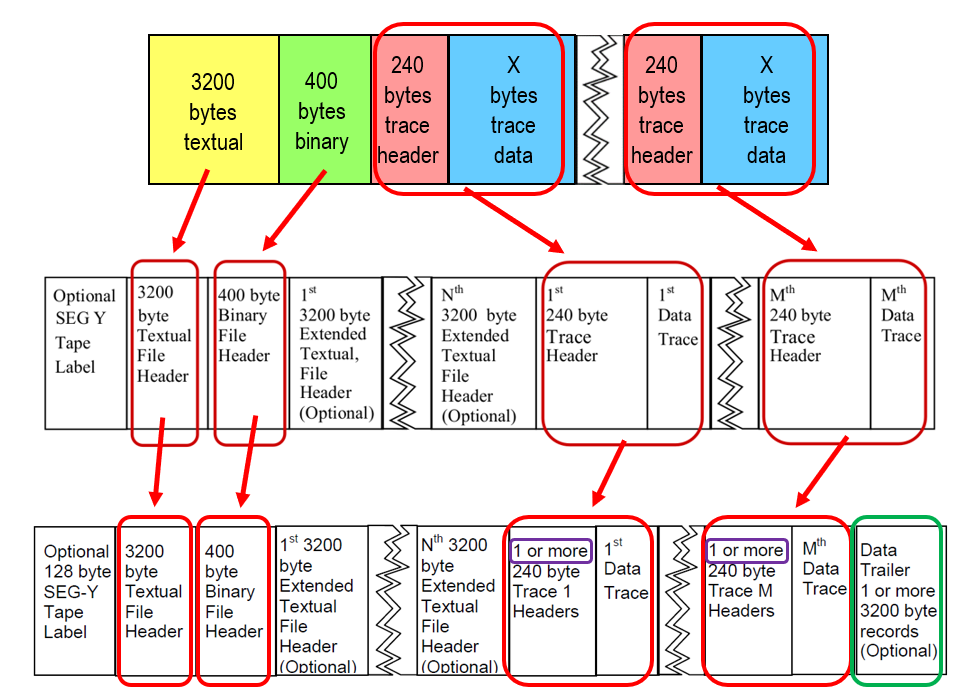
SEG-Y rev1 (middle row) has the same contents as rev0 (red boxes) and can have optional blocks: (1) a leading 128-byte tape label and (2) multiple 3200-byte blocks after the 400-byte binary header and before the first trace header.
At first glance, SEG-Y rev2 seems the same as rev1, with the addition of the Data Trailer (green box). However, please read the purple box in the trace header description: “1 or more.” In other words, SEG-Y rev2 traces can have more than one 240-byte trace header. In addition to this important change, rev2 data traces can have varying lengths.
All of us who are familiar with Seismic Unix know that SU trace header keys ns (number of samples in trace) and dt (sample interval in microseconds for this trace) are essential for processing SU data. However, the rarely discussed 400-byte Binary Header has several byte locations that are essential for any program to read a SEG-Y file (according to the SEG-Y standards documents):
And, for a program to read SEG-Y revision 1 or revision 2 files, the following byte locations are essential (again, according to the SEG-Y standards documents):
Seismic Unix has no program that lets the user read the Binary Header.
* The SEG-Y standards documents start counting byte locations in the 400-byte Binary Header at 3201 because these documents treat the Binary Header as an extension of the 3200 byte Textual Header. I start counting byte locations in the Binary Header at 1 (one) because I think of the Binary Header as a separate file. To ease your ability to compare byte locations in the Binary Header table, I use the official count but I also put my way of counting (starting at 1) in square brackets ([ ]).
The first Textual Header comes from an era of IBM punch cards. The format is exactly 3200 bytes, corresponding to 40 rows (40 cards) with 80 characters per card. Even when you do not see 80 characters in each row, know that unused characters are spaces. I mean to emphasize that each row really has exactly 80 characters.
The SEG-Y textual header, below, is from a marine acquisition project in Eugene Island, Gulf of Mexico. I include this example because this file’s format is typical of SEG-Y textual headers from commercial seismic data processors.
            C 1 PGS TENSOR SEG-Y

            C 2 LINE                 3440                                              C 2 L

            C 3 -------------------------------------------

            C 4 ACQ: DIAMOND GEO USING PGS EXPLORATION STRMR LEN:  6000 M

            C 5 AREA:  EUGENE ISLAND PHASE I     STRMR DEPTH:  9 M

            C 6 R/V:  MV EDISON & JONATHAN CHOUEST      GRP INT:  25 M

            C 7 AZMTH:  269.202356 DEGREES            GRPS/STRMR:  240

            C 8 SRC VOL & PRSR:   4770 CU IN, 2000 PSI    REC INSTR:  SYNTRAK 480

            C 9 SRC DEPTH:  7.5 M               FILT:  3HZ 6DB/OCT-218HZ 484DB/OCT

            C10 NO OF SRCS:  2                        REC LEN:  10752 MS

            C11

            C12 NR OFFSET:  185 M                     SAMP INT:  2 MS

            C13 STRMR TYPE:  TELEDYNE DIGITAL

            C14 NO OF STRMR:  3                       ACQ CLIENT CONTCT:  JOHN CRAMER,  DIAM

            C15 ---------------------------------------------------------------

            C16 NAV:  STARFIX & WADGPS COMPARISON     CEN MRDN:  93 0 .000W

            C17 DATUM:  SEA LEVEL                     ORIGIN COOR:  500000.00E

            C18 UNIT:  METERS                         SCALE FCTR:   .9996000000

            C19 PROCESSING:  PGS TENSOR HOUSTON, TX UNDER SUPERVISION OF  DIAMOND GEO

            C20 PROJECT:  EUGENE ISLAND PHASE I

            C21 PROCESSING SUPERVISOR:  DAVIS RATCLIFF

            C22

            C23 PROCESSING FLOW:

            C24 SEG-D REFORMAT,       RESAMPLE TO 4 MS

            C25 TRACE EDITING,        NAVIGATION MERGED WITH SEISMIC

            C26 HIGH PASS FILTER:  LOW CUT 2 HZ, LOW PASS 4 HZ

            C27 DATUM CORRECTION,     SPHERICAL DIVERGENCE & GAIN CORRECTION

            C28 FIRST BREAK MUTE,     DECONVOLUTION:  SPIKE, 2 WINDOW

            C29 TRACE BALANCING,      DMO STACK

            C30 INTERPOLATION TO 20 M SUBLINE SPACING,   CLEAN-UP MUTE

            C31 BANDPASS FILT:  LOW CUT           HIGH CUT

            C32      0 SEC:       3/5               80/100

            C33      5 SEC:       3/5               65/85

            C34      6 SEC:       3/5               50/70

            C35      8 SEC:       3/5               40/55

            C36     10 SEC:       3/5               35/50

            C37 GAIN DOWN:  -2 DB/SECOND

            C38 MIGRATE: ONE PASS CASCADED FINITE DIFFERENCE

            C39 GAIN RECOVERY: +2 DB/SECOND,  WATER BOTTOM REFERENCED CLEAN-UP MUTE

            C40 GLOBAL RELATIVE AMPLITUDE COMPENSATION
The upper two-thirds usually has project information, acquisition parameters, and sometimes geometry information. The bottom one-third sometimes has processing information. For a diagram of a typical SEG-Y textual header, see the SEG-Y rev2 reference document’s Table 1, “Textual File Header” (page 5).
The 400-byte Binary File Header record contains binary values relevant to the whole SEG-Y file. The values in the Binary File Header are defined as two-byte or four-byte, two's complement or unsigned integers, with the exception of IEEE double precision sample intervals in the optional SEG00001 trace header. Certain values in this header are crucial for the processing of the data in the file, particularly the sample interval, trace length, and format code. Revision 2.0 defines a few additional fields in the optional portion, as well as providing some clarification on the use of some existing entries.
The SEG-Y binary header table starts counting byte locations at 3201 because SEG-Y documents consider the binary header an extension of the first 3200 byte textual file header. Therefore, that is the numbering in the first column. The second column is byte length. The third column starts counting byte locations in the binary header at 1 (one) for convenience when counting these bytes as a separate file. When byte locations are stated in the Description, column 3 references are in square brackets ([ ]).
| Bytes | Length | Bytes | Description |
|---|---|---|---|
| 3201-3204 | 4 | 1-4 | Job identification number. |
| 3205-3208 | 4 | 5-8 | Line number. For 3-D poststack data, this will typically contain the in-line number. |
| 3209-3212 | 4 | 9-12 | Reel number. |
| 3213-3214 | 2 | 13-14 | Number of data traces per ensemble. Mandatory for prestack data. |
| 3215-3216 | 2 | 15-16 | Number of auxiliary traces per ensemble. Mandatory for prestack data. |
| 3217-3218 | 2 | 17-18 | Sample interval. Microseconds (µs) for time data, Hertz (Hz) for frequency data, meters (m) or feet (ft) for depth data. Mandatory for all data types. |
| 3219-3220 | 2 | 19-20 | Sample interval of original field recording. Microseconds (µs) for time data, Hertz (Hz) for frequency data, meters (m) or feet (ft) for depth data. |
| 3221-3222 | 2 | 21-22 | Number of samples per data trace.
Mandatory for all types of data. Note: The sample interval and number of samples in the Binary File Header should be for the primary set of seismic data traces in the file. |
| 3223-3224 | 2 | 23-24 | Number of samples per data trace for original field recording. |
| 3225-3226 | 2 | 25-26 | Data sample format code.
Mandatory for all data.
These formats are described in Appendix E of the SEG-Y revision 2 document. 1 = 4-byte IBM floating-point 2 = 4-byte, two's complement integer 3 = 2-byte, two's complement integer 4 = 4-byte fixed-point with gain (obsolete) 5 = 4-byte IEEE floating-point 6 = 8-byte IEEE floating-point 7 = 3-byte two's complement integer 8 = 1-byte, two's complement integer 9 = 8-byte, two's complement integer 10 = 4-byte, unsigned integer 11 = 2-byte, unsigned integer 12 = 8-byte, unsigned integer 15 = 3-byte, unsigned integer 16 = 1-byte, unsigned integer |
| 3227-3228 | 2 | 27-28 | Ensemble fold — The expected number of data traces per trace ensemble (e.g., the CMP fold). |
| 3229-3230 | 2 | 29-30 | Trace sorting code (i.e., type of ensemble): -1 = Other (should be explained in a user Extended Textual File Header stanza) 0 = Unknown 1 = As recorded (no sorting) 2 = CDP ensemble 3 = Single fold continuous profile 4 = Horizontally stacked 5 = Common source point 6 = Common receiver point 7 = Common offset point 8 = Common mid-point 9 = Common conversion point |
| 3231-3232 | 2 | 31-32 | Vertical sum code: 1 = no sum, 2 = two sum, …, N = M-1 sum (M = 2 to 32,767) |
| 3233-3234 | 2 | 33-34 | Sweep frequency at start (Hz). |
| 3235-3236 | 2 | 35-36 | Sweep frequency at end (Hz). |
| 3237-3238 | 2 | 37-38 | Sweep length (ms). |
| 3239-3240 | 2 | 39-40 | Sweep type code: 1 = linear 2 = parabolic 3 = exponential 4 = other |
| 3241-3242 | 2 | 41-42 | Trace number of sweep channel. |
| 3243-3244 | 2 | 43-44 | Sweep trace taper length in milliseconds at start if tapered (the taper starts at zero time and is effective for this length). |
| 3245-3246 | 2 | 45-46 | Sweep trace taper length in milliseconds at end (the ending taper starts at sweep length minus the taper length at end). |
| 3247-3248 | 2 | 47-48 | Taper type: 1 = linear 2 = cosine squared 3 = other |
| 3249-3250 | 2 | 49-50 | Correlated data traces: 1 = no 2 = yes |
| 3251-3252 | 2 | 51-52 | Binary gain recovered: 1 = yes 2 = no |
| 3253-3254 | 2 | 53-54 | Amplitude recovery method: 1 = none 2 = spherical divergence 3 = AGC 4 = other |
| 3255-3256 | 2 | 55-56 | Measurement system: If Location Data stanzas are included in the file, this entry would normally agree with the
Location Data stanza. If there is a disagreement, the last Location Data stanza is the controlling authority. If units are mixed,
e.g., meters on surface, feet in depth, then a Location Data stanza is mandatory. 1 = Meters 2 = Feet |
| 3257-3258 | 2 | 57-58 | Impulse signal polarity 1 = Increase in pressure or upward geophone case movement gives negative number on trace. 2 = Increase in pressure or upward geophone case movement gives positive number on trace. |
| 3259-3260 | 2 | 59-60 | Vibratory polarity code: Seismic signal lags pilot signal by: 1 = 337.5° to 22.5° 2 = 22.5° to 67.5° 3 = 67.5° to 112.5° 4 = 112.5° to 157.5° 5 = 157.5° to 202.5° 6 = 202.5° to 247.5° 7 = 247.5° to 292.5° 8 = 292.5° to 337.5° |
| - | - | - | - |
| - | - | - | The SEG-Y Revision 1 (rev1) and Revision 2 (rev2) locations below were unassigned in rev0. |
| - | - | - | - |
| 3261-3264 | 4 | 61-64 | Extended number of data traces per ensemble. If nonzero, this overrides the number of data traces per ensemble in bytes 3213-3214 [13-14]. |
| 3265-3268 | 4 | 65-68 | Extended number of auxiliary traces per ensemble. If nonzero, this overrides the number of auxiliary traces per ensemble in bytes 3215-3216 [15-16]. |
| 3269-3272 | 4 | 69-72 | Extended number of samples per data trace. If nonzero, this overrides the number of samples per data trace in bytes 3221-3222 [21-22]. |
| 3273-3280 | 8 | 73-80 | Extended sample interval, IEEE double precision (64-bit). If nonzero, this overrides the sample interval in bytes 3217-3218 [17-18] with the same units. |
| 3281-3288 | 8 | 81-88 | Extended sample interval of original field recording, IEEE double precision (64-bit). If nonzero, this overrides the sample interval of original field recording in bytes 3219-3220 [19-20] with the same units. |
| 3289-3292 | 4 | 89-92 | Extended number of samples per data trace in original recording. If nonzero, this overrides the number of samples per data trace in original recording in bytes 3223-3224 [23-24]. |
| 3293-3296 | 4 | 93-96 | Extended ensemble fold. If nonzero, this overrides ensemble fold in bytes 3227-3228 [27-28]. |
| 3297-3300 | 4 | 97-100 | The integer constant 1690906010 (0102030416). This is used to allow unambiguous detection
of the byte ordering to expect for this SEG-Y file. For example, if this field reads as 6730598510 (0403020116)
then the bytes in every Binary File Header, Trace Header and Trace Data field must be reversed as they are read, i.e., converting
the endian-ness of the fields. If it reads 3362099510 (0201040316) then consecutive pairs of bytes need to
be swapped in every Binary File Header, Trace Header and Trace Data field. The byte ordering of all other portions (the Extended Textual Header and Data Trailer) of the SEG-Y file is not affected by this field. |
| 3301-3500 | 200 | 101-300 | Unassigned |
| 3501-3501 | 1 | 301-301 | Major SEG-Y Format Revision Number. This is an 8-bit unsigned value. Thus for SEG-Y Revision 2.0, as defined in this document, this will be recorded as 0216. This field is mandatory for all versions of SEG-Y, although a value of zero indicates "traditional" SEG-Y conforming to the 1975 standard. |
| 3502-3502 | 1 | 302-302 | Minor SEG-Y Format Revision Number. This is an 8-bit unsigned value with a radix point between the first and second bytes. Thus for SEG-Y Revision 2.0, as defined in this document, this will be recorded as 0016. This field is mandatory for all versions of SEG-Y. |
| - | - | - | Note that bytes 3501 [301] and 3502 [302] were combined in revision 1.
For the sake of completeness, I include the revision 1 description of bytes 3501-3502 [301-302] here: SEG-Y Format Revision Number. This is a 16-bit unsigned value with a Q-point between the first and second bytes. Thus for SEG-Y Revision 1.0, as defined in this document, this will be recorded as 010016. This field is mandatory for all versions of SEG-Y, although a value of zero indicates "traditional" SEG-Y conforming to the 1975 standard. |
| 3503-3504 | 2 | 303-304 | Fixed length trace flag. A value of one indicates that all traces in this SEG-Y file are guaranteed to have the same sample interval, number of trace header blocks and trace samples, as specified in Binary File Header bytes 3217-3218 [17-18] or 3281-3288 [81-88], 3517-3518 [317-318], and 3221-3222 [21-22] or 3289-3292 [89-92]. A value of zero indicates that the length of the traces in the file may vary and the number of samples in bytes 115-116 of the Standard SEG-Y Trace Header and, if present, bytes 137-140 of SEG-Y Trace Header Extension 1 must be examined to determine the actual length of each trace. This field is mandatory for all versions of SEG-Y, although a value of zero indicates "traditional" SEG-Y conforming to the 1975 standard. Irrespective of this flag, it is strongly recommended that correct values for the number of samples per trace and sample interval appear in the appropriate trace Trace Header locations. |
| 3505-3506 | 2 | 305-306 | Number of 3200-byte, Extended Textual File Header records following the Binary Header. If bytes 3521-3528 [321-328] are
nonzero, that field overrides this one. A value of zero indicates there are no Extended Textual File Header records (i.e., this file
has no Extended Textual File Header(s)). A value of -1 indicates that there are a variable number of Extended Textual File Header
records and the end of the Extended Textual File Header is denoted by an ((SEG: EndText)) stanza in the final record (Section 6.2).
A positive value indicates that there are exactly that many Extended Textual File Header records. Note that, although the exact number of Extended Textual File Header records may be a useful piece of information, it will not always be known at the time the Binary Header is written and it is not mandatory that a positive value be recorded here or in bytes 3521-3528 [321-328]. It is however recommended to record the number of records if possible as this makes reading more effective and supports direct access to traces on disk files. In the event that this number exceeds 32767, set this field to -1 and bytes 3521-3528 [321-328] to 3600+3200*(number of Extended Textual File Header records). Add a further 128 if a SEG-Y Tape Label is present. |
| 3507-3510 | 4 | 307-310 | Maximum number of additional 240 byte trace headers. A value of zero indicates there are no additional 240 byte trace headers. The actual number for a given trace may be supplied in bytes 157-158 of SEG-Y Trace Header Extension 1. |
| 3511-3512 | 2 | 311-312 | Time basis code: 1 = Local 2 = GMT (Greenwich Mean Time) 3 = Other, should be explained in a user defined stanza in the Extended Textual File Header 4 = UTC (Coordinated Universal Time) 5 = GPS (Global Positioning System Time) |
| 3513-3520 | 8 | 313-320 | Number of traces in this file or stream. (64-bit unsigned integer value) If zero, all bytes in the file or stream are part of this SEG-Y dataset. |
| 3521-3528 | 8 | 321-328 | Byte offset of first trace relative to start of file or stream if known, otherwise zero. (64-bit unsigned integer value) This byte count will include the initial 3600 bytes of the Textual and this Binary File Header plus the Extended Textual Header if present. When nonzero, this field overrides the byte offset implied by any nonnegative number of Extended Textual Header records present in bytes 3505-3506 [305-306]. |
| 3529-3532 | 4 | 329-332 | Number of 3200-byte data trailer stanza records following the last trace (4 byte signed integer). A value of 0 indicates there are no trailer records. A value of -1 indicates an undefined number of trailer records (0 or more) following the data. It is, however, recommended to record |
| 3533-3600 | 68 | 333-400 | Unassigned |
| SU key | Length | Bytes | Description |
|---|---|---|---|
| tracl | 4 | 1-4 | Trace sequence number within line -- Numbers continue to increase if the same line continues across multiple SEG-Y files. |
| tracr | 4 | 5-8 | Trace sequence number within SEG-Y file -- Each file starts with trace sequence one. |
| fldr | 4 | 9-12 | Original field record number. |
| tracf | 4 | 13-16 |
Trace number within the original field record. If supplying multi-cable data with
identical channel numbers on each cable, either supply the cable ID number in
bytes 153-156 of SEG-Y Trace Header Extension 1 or enter (cable-1) * nchan_per_cable + channel_no here. |
| ep | 4 | 17-20 | Energy source point number -- Used when more than one record occurs at the same effective surface location. It is recommended that the new entry defined in Trace Header bytes 197-202 be used for shotpoint number. |
| cdp | 4 | 21-24 | Ensemble number (i.e., CDP, CMP, CRP, etc.) |
| cdpt | 4 | 25-28 | Trace number within the CDP ensemble -- Each ensemble starts with trace number one. |
| trid | 2 | 29-30 |
Trace identification code: -1=Other 0=Unknown 1=Time domain seismic data 2=Dead 3=Dummy 4=Time break 5=Uphole 6=Sweep 7=Timing 8=Waterbreak 9=Near-field gun signature 10=Far-field gun signature 11=Seismic pressure sensor 12=Multicomponent seismic sensor -- Vertical component 13=Multicomponent seismic sensor -- Crossline component 14=Multicomponent seismic sensor -- Inline component 15=Rotated multicomponent seismic sensor -- Vertical component 16=Rotated multicomponent seismic sensor -- Transverse component 17=Rotated multicomponent seismic sensor -- Radial component 18=Vibrator reaction mass 19=Vibrator baseplate 20=Vibrator estimated ground force 21=Vibrator reference 22=Time-velocity pairs 23=Time-depth pairs 24=Depth-velocity pairs 25=Depth domain seismic data 26=Gravity potential 27=Electric field -- Vertical component 28=Electric field -- Crossline component 29=Electric field -- Inline component 30=Rotated electric field -- Vertical component 31=Rotated electric field -- Transverse component 32=Rotated electric field -- Radial component 33=Magnetic field -- Vertical component 34=Magnetic field -- Crossline component 35=Magnetic field -- Inline component 36=Rotated magnetic field -- Vertical component 37=Rotated magnetic field -- Transverse component 38=Rotated magnetic field -- Radial component 39=Rotational sensor -- Pitch 40=Rotational sensor -- Roll 41=Rotational sensor -- Yaw 42 ... 255=Reserved 256 ... N=optional use, (maximum N = 16,383) N+16,384=Interpolated, i.e., not original, seismic trace. |
| nvs | 2 | 31-32 | Number of vertically summed traces yielding this trace. (1 is one trace, 2 is two summed traces, etc.) |
| nhs | 2 | 33-34 | Number of horizontally stacked traces yielding this trace. (1 is one trace, 2 is two stacked traces, etc.) |
| duse | 2 | 35-36 |
Data use: 1=production 2=test |
| offset | 4 | 37-40 | Distance from source point center to receiver group center (negative if opposite to direction in which line is shot). |
| gelev | 4 | 41-44 | Elevation of receiver group. This is, of course, normally equal to or lower than the surface elevation at the group location. |
| selev | 4 | 45-48 | Surface elevation at source location. |
| sdepth | 4 | 49-52 | Source depth below surface. |
| gdel | 4 | 53-56 | Seismic Datum elevation at receiver group. (If different from the survey vertical datum, Seismic Datum should be defined through a vertical Coordinate Reference System (CRS) in an extended textual stanza.) |
| sdel | 4 | 57-60 | Seismic Datum elevation at source. (As above.) |
| swdep | 4 | 61-64 | Water column height at source location (at time of source event). |
| gwdep | 4 | 65-68 | Water column height at receiver group location (at time of recording of first source event into that receiver). |
| scalel | 2 | 69-70 |
Scalar to be applied to all elevations and depths specified in Standard Trace
Header bytes 41-68 to give the real value. Scalar = 1, +/- 10, +/- 100, +/- 1000, or +/- 10,000. Positive=multiplier, Negative=divisor. A value of zero is assumed to be a scalar value of 1. |
| scalco | 2 | 71-72 |
Scalar to be applied to all coordinates specified in Standard Trace Header bytes
73-88 and to Standard Trace Header bytes 181-188 to give the real value. Scalar = 1, +/- 10, +/- 100, +/- 1000, or +/- 10,000. Positive=multiplier, Negative=divisor. A value of zero is assumed to be a scalar value of 1. |
| sx | 4 | 73-76 | Source coordinate -- X. |
| sy | 4 | 77-80 | Source coordinate -- Y. |
| gx | 4 | 81-84 | Group coordinate -- X. |
| gy | 4 | 85-88 | Group coordinate -- Y. |
| - | - | - |
Regarding preceding bytes 73-88: The coordinate reference system (CRS) should be
identified through an Extended Textual Header (see Rev2, Appendix D-1). If the coordinate units are in seconds of arc, decimal degrees or DMS, the X values represent longitude and the Y values represent latitude. A positive value designates east of Greenwich Meridian or north of the equator and a negative value designates south or west. |
| counit | 2 | 89-90 |
Coordinate units: 1=length (meters or feet as specified in Binary File Header bytes 3255-3256 [55-56] and in Extended Textual Header if Location Data are included in the file). 2=Seconds of arc (deprecated) 3=Decimal degrees (preferred degree representation) 4=Degrees, minutes, seconds (DMS). Note: To encode +/- DDDMMSS set bytes 73-88 = +/- DDD*10^4 + MM*10^2 + SS with bytes 71-72 set to 1; to encode +/- DDDMMSS.ss set bytes 73-78 = +/- DDD*10^6 + MM*10^4 + SS*10^2 + ss with bytes 71-72 set to -100. |
| wevel | 2 | 91-92 | Weathering velocity (ft/s or m/s). |
| swevel | 2 | 93-94 | Subweathering velocity (ft/s or m/s). |
| sut | 2 | 95-96 | Uphole time at source (ms). |
| gut | 2 | 97-98 | Uphole time at group (ms). |
| sstat | 2 | 99-100 | Source static correction (ms). |
| gstat | 2 | 101-102 | Group static correction (ms). |
| tstat | 2 | 103-104 | Total static applied (ms). (Zero if no static has been applied.) |
| laga | 2 | 105-106 | Lag time A (ms). Time in milliseconds between end of 240-byte trace ID header and time break. The value is positive if time break occurs after the end of header, negative if time break occurs before the end of header. Time break is defined as the initiation pulse that may be recorded on an auxiliary trace or as otherwise specified by the recording system. |
| lagb | 2 | 107-108 | Lag Time B (ms). Time in milliseconds between time break and the initiation time of the energy source. May be positive or negative. |
| delrt | 2 | 109-110 | Delay recording time (ms). Time in milliseconds between initiation time of energy source and the time when recording of data samples begins. In SEG-Y rev0, this entry was intended for deep-water work if data recording does not start at zero time. The entry can be negative to accommodate negative start times (i.e., data recorded before time zero, presumably as a result of static application to the data trace). If a non-zero value (negative or positive) is recorded in this entry, a comment to that effect should appear in the Textual File Header. |
| muts | 2 | 111-112 | Mute time -- start (ms). |
| mute | 2 | 113-114 | Mute time -- end (ms). |
| ns | 2 | 115-116 | Number of samples in this trace. |
| dt | 2 | 117-118 | Sample interval in µsec for this trace. |
| gain | 2 | 119-120 |
Gain type of field instruments: 1=fixed 2=binary 3=floating point 4 ... N = optional use |
| igc | 2 | 121-122 | Instrument gain constant (dB). |
| igi | 2 | 123-124 | Instrument early or initial gain (dB). |
| corr | 2 | 125-126 |
Correlated: 1=no 2=yes |
| sfs | 2 | 127-128 | Sweep frequency at start (Hz). |
| sfe | 2 | 129-130 | Sweep frequency at end (Hz). |
| slen | 2 | 131-132 | Sweep length (ms). |
| styp | 2 | 133-134 |
Sweep type: 1=linear 2=parabolic 3=exponential 4=other |
| stas | 2 | 135-136 | Sweep trace taper length at start (ms). |
| stae | 2 | 137-138 | Sweep trace taper length at end (ms). |
| tatyp | 2 | 139-140 |
Taper type: 1=linear 2=cosine squared 3=other |
| afilf | 2 | 141-142 | Alias filter frequency (Hz), if used. |
| afils | 2 | 143-144 | Alias filter slope (dB/octave). |
| nofilf | 2 | 145-146 | Notch filter frequency (Hz), if used. |
| nofils | 2 | 147-148 | Notch filter slope (dB/octave). |
| lcf | 2 | 149-150 | Low cut frequency (Hz), if used. |
| hcf | 2 | 151-152 | High cut frequency (Hz), if used. |
| lcs | 2 | 153-154 | Low cut slope (dB/octave). |
| hcs | 2 | 155-156 | High cut slope (dB/octave). |
| year | 2 | 157-158 | Year data recorded. For SEG-Y revisions beyond rev0, the year should be recorded as the complete 4-digit Gregorian calendar year (i.e., the year 2001 should be recorded as 200110 (7D116)). |
| day | 2 | 159-160 | Day of year (Julian day for GMT and UTC time basis). |
| hour | 2 | 161-162 | Hour of day (24 hour clock). |
| minute | 2 | 163-164 | Minute of hour. |
| sec | 2 | 165-166 | Second of minute. |
| timbas | 2 | 167-168 |
Time basis code. If non-zero, overrides Binary File Header bytes 3511-3512 [bytes 311-312] 1=Local 2=GMT (Greenwich Mean Time) 3=Other 4=UTC (Coordinated Universal Time) 5=GPS (Global Positioning System Time) |
| trwf | 2 | 169-170 | Trace weighting factor -- Defined as 2-N volts for the least significant bit. (N = 0, 1, ..., 32767.) |
| grnors | 2 | 171-172 | Geophone group number of roll switch position one. |
| grnofr | 2 | 173-174 | Geophone group number of trace number one within original field record. |
| grnlof | 2 | 175-176 | Geophone group number of last trace within original field record. |
| gaps | 2 | 177-178 | Gap size (total number of groups dropped). |
| ofrav | 2 | 179-180 |
Over travel associated with taper at beginning or end of line: 1=down (or behind) 2=up (or ahead). |
| - | 60 | 181-240 | SEG-Y Revison 0: Unassigned -- for optional information. |
| - | - | - | - |
| - | - | - | Some extended SU header locations follow. These were created before SEG-Y Revision 1 (Rev1). |
| - | - | - | - |
| d1 | 4 | 181-184 | (float) sample spacing for non-seismic data |
| f1 | 4 | 185-188 | (float) first sample location for non-seismic data |
| d2 | 4 | 189-192 | (float) sample spacing between traces |
| f2 | 4 | 193-196 | (float) first trace location |
| ungpow | 4 | 197-200 | (float) negative of power used for dynamic range compression |
| unscale | 4 | 201-204 | (float) reciprocal of scaling factor to normalize range |
| ntr | 4 | 205-208 | number of traces |
| mark | 2 | 209-210 | mark selected traces |
| shortpad | 2 | 211-212 | alignment padding |
| unass | 28 | 213-240 | unassigned |
| - | - | - | - |
| - | - | - | SEG-Y Revision 1 (Rev1) locations follow |
| - | - | - | - |
| - | 4 | 181-184 | X-coordinate of ensemble (CDP) position of this trace (scalar in Trace Header bytes 71-72 applies). The coordinate reference system should be identified through an extended header Location Data stanza (Ref: rev1, section D-1). |
| - | 4 | 185-188 | Y-coordinate of ensemble (CDP) position of this trace (scalar in Trace Header bytes 71-72 applies). The coordinate reference system should be identified through an extended header Location Data stanza (Ref: rev1, section D-1). |
| - | 4 | 189-192 | For 3-D poststack data,this field should be used for the in-line number. If one in-line per SEG-Y file is being recorded, this value should be the same for all traces in the file and the same value will be recorded in bytes 3205-3208 of the Binary File Header. |
| - | 4 | 193-196 | For 3-D poststack data, this field should be used for the cross-line number. This will typically be the same value as the ensemble (CDP) number in Trace Header bytes 21-24, but this does not have to be the case. |
| - | 4 | 197-200 | Shotpoint number -- This is probably only applicable to 2-D poststack data. Note that it is assumed that the shotpoint number refers to the source location nearest to the ensemble (CDP) location for a particular trace. If this is not the case, there should be a comment in the Textual File Header explaining what the shotpoint number actually refers to. |
| - | 2 | 201-202 | Scalar to be applied to shotpoint number in Trace Header bytes 197-200 to give the real value. If positive, scalar is used as a multiplier; if negative, scalar is used as a divisor; if zero, the shotpoint number is not scaled (i.e., it is an integer. A typical value will be -10, allowing shotpoint numbers with one decimal digit to the right of the decimal point.) |
| - | 2 | 203-204 |
Trace value measurement unit: -1=Other (should be described in Data Sample Measurement Units stanza) 0=Unknown 1=Pascal (Pa) 2=Volts (V) 3=Millivolts (mV) 4=Amperes (A) 5=Meters (m) 6=Meters per second (m/s) 7=Meters per second squared (m/s2) 8=Newton (N) 9=Watt (W) |
| - | 6 | 205-210 | Transduction Constant -- The multiplicative constant used to convert the Data Trace samples to the Transduction Units (specified in Trace Header bytes 211-212). The constant is encoded as a four-byte, two's complement integer (bytes 205-208) which is the mantissa and a two-byte, two's complement integer (bytes 209-210) which is the power of ten exponent (i.e., Bytes 205-208 * 10**Bytes 209-210). |
| - | 2 | 211-212 |
Transduction units -- the unit of measurement of the Data Trace samples after they have been
multiplied by the Transduction Constant specified in Trace Header bytes 205-210. -1=Other (should be described in Data Sample Measurement Unit stanza (Ref: rev1, p.36)) 0=Unknown 1=Pascal (Pa) 2=Volts (V) 3=Millivolts (mV) 4=Amperes (A) 5=Meters (m) 6=meters per second (m/s) 7=Meters per second squared (m/s2) 8=Newton (N) 9=Watt (W) |
| - | 2 | 213-214 | Device/Trace Identifier -- The unit number or id number of the device associated with the Data Trace (i.e., 4368 for vibrator serial number 4368 or 20316 for gun 16 on string 3 on vessel 2). This field allows traces to be associated across trace ensembles independently of the trace number (Trace Header bytes 25-28). |
| - | 2 | 215-216 | Scalar to be applied to times specified in Trace Header bytes 95-114 to give the true time value in milliseconds. Scalar = 1, +10, +100, +1000, or +10,000. If positive, scalar is used as a multiplier; if negative, scalar is used as a divisor. A value of zero is assumed to be a scalar value of 1. |
| - | 2 | 217-218 |
Source Type/Orientation -- Defines the type and orientation of the energy source. The terms
vertical, cross-line, and in-line refer to the three axes of an orthogonal system. The absolute
azimuthal orientation of the coordinate system axes can be defined in the Bin Grid Definition
Stanza (Ref: rev1, p.27) -1 to -n = Other (should be described in Source Type/Orientation stanza (Ref: rev1, p.38)) 0 = Unknown 1 = Vibratory - Vertical orientation 2 = Vibratory - Cross-line orientation 3 = Vibratory - In-line orientation 4 = Impulsive - Vertical orientation 5 = Impulsive - Cross-line orientation 6 = Impulsive - In-line orientation 7 = Distributed Impulsive - Vertical orientation 8 = Distributed Impulsive - Cross-line orientation 9 = Distributed Impulsive - Inline orientation |
| - | 6 | 219-224 | Source energy direction with respect to the source orientation -- The positive orientation direction is in bytes 217-218 of the Trace Header. The energy direction is encoded in tenths of degrees (i.e., 347.8° is encoded as 3478). |
| - | 6 | 225-230 |
Source measurement -- Describes the source effort used to generate the trace. The measurement can
be simple, qualitative measurements such as the total weight of explosive used or the peak air gun
pressure or the number of vibrators times during the sweep duration. Although these simple
measurements are acceptable, it is preferable to use true measurement units of energy or work. The constant is encoded as a four-byte, two's complement integer (bytes 225-228) which is the mantissa and a two-byte, two's complement integer (bytes 229-230) which is the power of ten exponent (i.e., Bytes 225-228 * 10**Bytes 229-230). |
| - | 2 | 231-232 |
Source measurement unit -- The unit used for Source Measurement, trace header bytes 225-230. -1=Other (should be described in Source Measurement Unit stanza (Ref: rev1, p.39)) 0=unknown 1=Joule (J) 2=Kilowatt (kW) 3=Pascal (Pa) 4=Bar (Bar) 4=Bar-meter (Bar-m) 5=Newton (N) 6=Kilogram (kg) |
| - | 8 | 233-240 | Unassigned -- For optional information. |